Wind Load On Roof Screen Wall

Wind Uplift Forces On Roof Canopies Artiststudiocanopy002 Cantilever Canopy Structural Design Building Entrance Artist S Canopy Design Steel Canopy Wood Canopy

Image Result For Simpson Wind Fasteners On Homes Porch Rafter On Sheathing To Ledger Roof Truss Design Roof Framing Roof Design

Cmu Wall Reinforcement Google Search Retaining Wall Design Concrete Retaining Walls Concrete Block Retaining Wall

Stopanel Metal

Steel Stud Parapet Old Timer Wood Blocking And A Cant Anchored To The Structural Deck Restrain Architecture Details Roof Construction Architecture Building

A Curtain Wall System Is An Outer Covering Of A Building In Which The Outer Walls Are Non Structural But Merel Wall Systems Curtain Wall Curtain Wall Detail

Asce 7 10 provides two methods for wind load calculation.
Wind load on roof screen wall.

Danpal Vrs System Cladding From Danpal Cladding Rainscreen Cladding Architectural Section
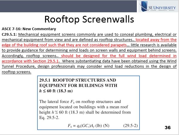
Wind Loads On Screen Walls And Roof Top Equipment Continuing Education Pdh For Structural Engineers Se University

Pin By Jd Mcbride On Church Look Rafter Ridge Board Building Roof

Guidelines For Disaster Resilient Buildings Structures Uap Emergency Architects Resilience Building Structure Disasters
Source : pinterest.com
